Perform the following tests:
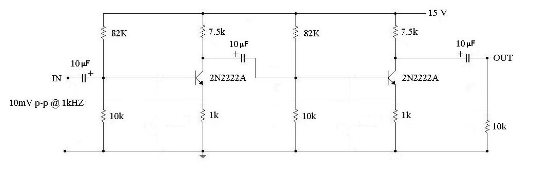
1. Measure the voltages at the Emitter, Base and Collector of both transistors
2. Apply the 1kHz. test tone, measure the signal voltage at the collector of the first transistor USING YOUR OSCILLOSCOPE and calculate the gain of the first stage
3. Now measure the output signal level at the collector of the second transistor and calculate both the second stage gain and the overall gain of your 2-stage amplifier
Here is the 2-stage amplifier with a LOAD added to it's output
Perform the following tests:
1. REPEAT all your signal measurements from the section above and COMPARE your results
2. How has adding the LOAD affected your results ? Explain the differences ?
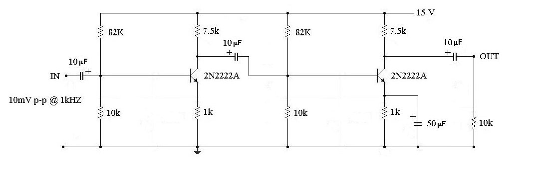
Here is the loaded circuit with an emitter BYPASS CAPACITOR added to the second stage
Perform the following tests:
1. REPEAT all your signal measurements and again COMPARE your results
2. How has adding the bypass capacitor affected your results ? Explain the differences ?
Perform the following tests to DETERMINE THE FREQUENCY RESPONSE of your 2-stage amplifier
1. Connect your Oscilloscope to measure the signal voltage across the LOAD.
2. While maintining the SAME input signal voltage, measure the OUTPUT voltage for each of the following frequencies 20Hz., 50Hz.,100Hz.,300Hz., 1kHz.,3kHz.,5kHz.,10kHz.,20kHz.,50kHz.
3. Plot the Frequency Response of your 2-stage amplifier on an appropriate graph.