It accepts input from two devices that are easy to acquire, a passive infrared sensor (used in common household alarm systems, any type will do as long as it is rated for 12 volts) and a magnetic switch (household alarm system component, also).
It is important to mount the PIR sensor so that if there is movement in the room it will be detected !
If the unit is used for airconditioning control, additional magnetic switches can be mounted on windows and wired in series (for N.C. switches) or parallel (N.O. switches) with the door switch, so unit will not run with windows open.
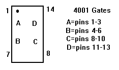
 Refer to figure and Schematic for gate identification.
Provided that the door is closed, the signal from the PIR sensor sets the SR latch (IC1, gates C & D) to tell the appliance to operate (this only happens if there is movement in the room).
IC4 is a compressor protection timer, when the unit is switched off this timer is initiated (the red LED indicates it is active) if the unit is instructed to turn on, it will not do so till the time expires and the red LED goes out, this avoids repeated instantaneous switching of the system.
Timer IC5 keeps the appliance running when the door is opened (after all, there may be several people in the room). If the door is left open, the appliance stops when this timer expires. If the door is shut when this timer expires AND if there has been no movement in the room during the period since it was shut, then the appliance turns off.
IC1(gate A) and IC3(gate C) with the associated RC components produce a positive pulse at pin 10 of IC2 and pin 4 of IC6 whenever the door is either opened of closed, this resets/starts timer IC5 and if the timer was ALREADY RUNNING, sends a pulse to reset the SR latch. This is needed to ensure the latch is reset if the door is opened and shut more than once during the timed interval.
The reason IC6(gates B & C) is included (instead of connecting pin 10 of IC2 to pin 12 of IC2) has to do with stability. The timer was prone to re-trigger itself (coupling in IC2 (gate D).
Constuction Notes
Schematic Diagram
 Back to my Homepage.